Blog

by

Does Your Business Comply with Harmonic Limit Values?

The “SERVICE QUALITY REGULATION REGARDING ELECTRICITY DISTRIBUTION AND RETAIL SALES” published in the Official Gazette dated 21 December 2012 and numbered 28504 sets the definitions and rules regarding energy quality. According to this regulation, distribution companies are obliged to provide their subscribers with the voltage quality conditions specified in the TS EN 50160 Standard. On the other hand, subscribers are obliged to comply with the current harmonic limit values specified in the IEEE 519 Standard (Table 11). According to Article 23 – Clause three, it is stated that if the user, who causes harmonic distortion in the network, does not comply with the limit values until the end of the given time, he will be disconnected. You can download the relevant regulation from the link below.

https://www.epdk.gov.tr/Detay/DownloadDocument?id=y/bTg3OJP/s=

LIMIT VALUES OF VOLTAGE HARMONICS ACCORDING TO TS EN 50160

TABLE-11 LIMIT VALUES ACCORDING TO MAXIMUM LOAD CURRENT (IL) FOR CURRENT HARMONICS

Isc / IL3-5
7-9
11-13-1517-19-2123-25-27
29-31-33
35 ve üzeriTTB
(TDD)
< 20421,50,60,35
20 < 5073,52,510,58
50 < 100104,541,50,712
100 < 1000125,552115
> 100015762,51,420
CURRENT HARMONIC LIMIT VALUES ACCORDING TO IL MAXIMUM LOAD CURRENT

Even harmonics are limited to 25% of the value defined for the next odd harmonic.

What do the values in the table represent?

The values in the table represent the limits of the current harmonics drawn by the enterprise from the network. In order to determine which limit values are, first of all, the ISC / IL value must be calculated. The ISC value is the short-circuit current at the network connection point of the enterprise (this value can be calculated by the relevant distribution company), and the IL value is the basic component value of the maximum load current drawn from the network for 1 year. It is not always possible to determine these values precisely. In such cases, approximate values are used. The values in the first line represent the order of the harmonic component, and the values in the other lines represent the percentage ratios of the measured harmonic currents to the IL value.

What is TTB (TDD)?
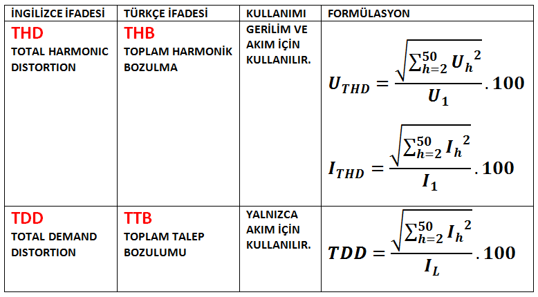
The term TTB (Total Demand Distortion in English) is often confused with the term THD. TTB represents the ratio of the vector sum of the harmonic distortions in the current to the IL value.

HARMONIC TERMS

HOW LONG SHOULD THE HARMONIC MEASUREMENT TIME BE?
The harmonic measurement period is defined as “one-week uninterrupted measurement time defined in TS EN 61000-4-30” in the relevant regulation.

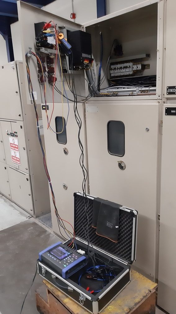
WHERE SHOULD THE HARMONIC MEASUREMENT BE PLACED?
The harmonic measurement location must be the mains connection point of the facility. This point is usually the point where the meter is the basis for billing. If there is a transformer between the mains connection point and the measurement point, the measurements taken from the low voltage main switch of the facility should be reduced to the mains connection point.

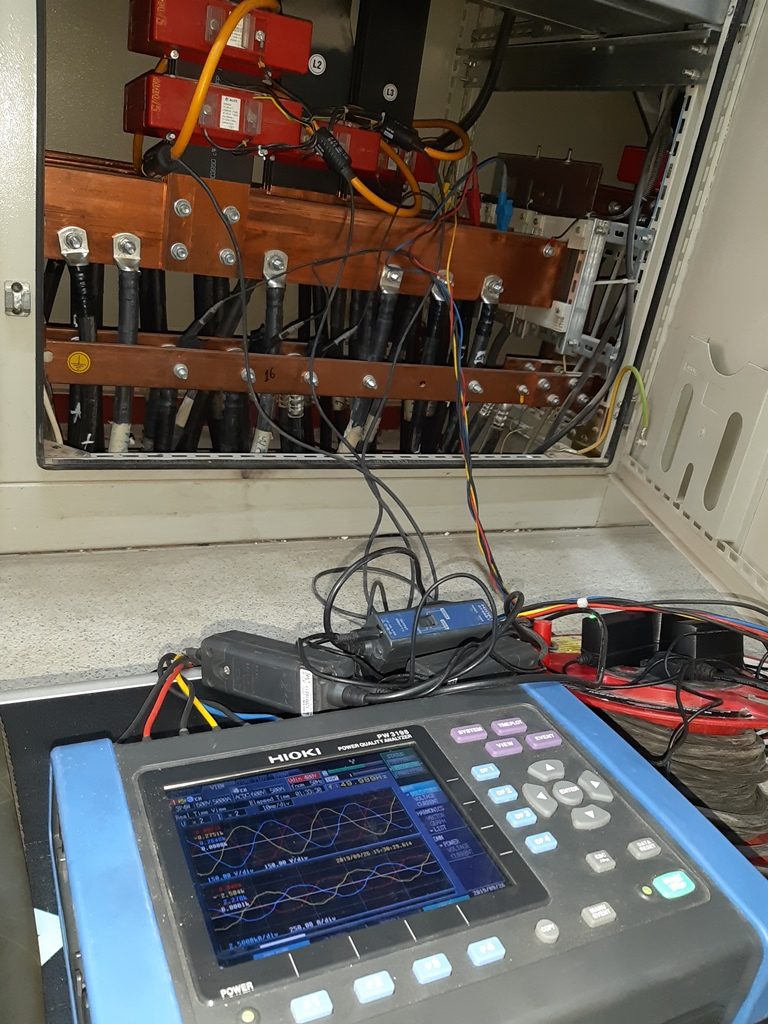
WHAT ARE THE FEATURES SHOULD A HARMONIC MEASUREMENT DEVICE HAVE?
The characteristics that the harmonic measuring device must have are determined in the IEC 61000-4-30 standard. According to the relevant standard, the device to be used in harmonic measurement must measure in Class A properties.

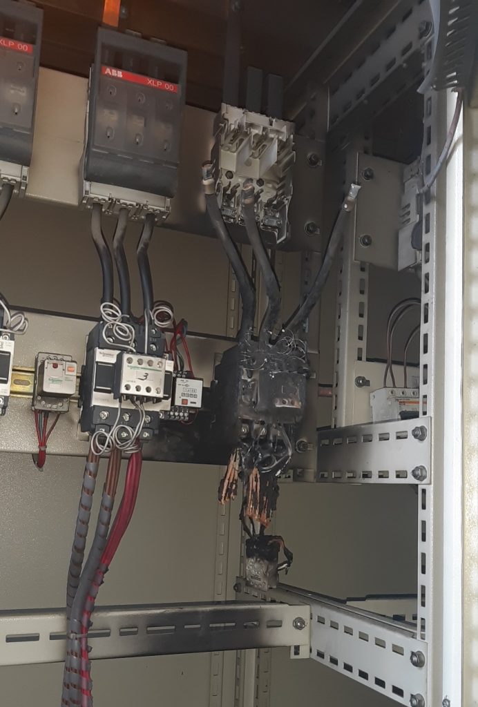
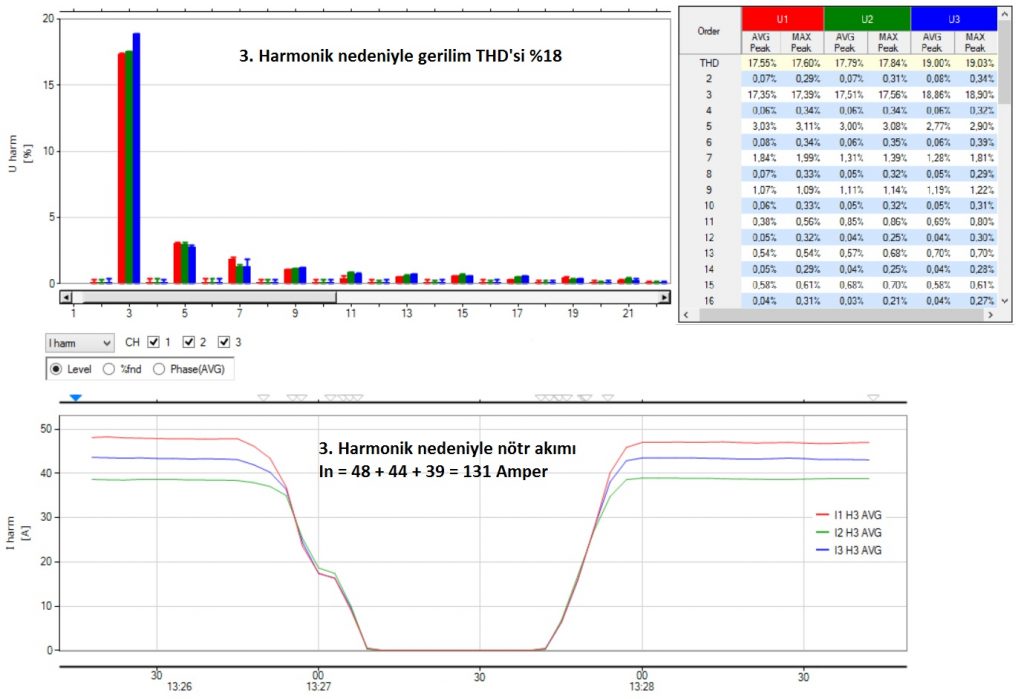
As a result of the measurements, it is checked whether the harmonic values ​​of the facility exceed the limit values. If it is determined that the limit values ​​are exceeded, the source causing this should be determined and the most appropriate solution should be designed.

HAVE HARMONIC MEASUREMENT AND ANALYSIS DONE IN YOUR FACILITY. COMPLY WITH HARMONIC LEGISLATION. USE MORE RELIABLE AND MORE EFFICIENT ENERGY.

by

What is harmonic?

What is harmonic? Harmonic is briefly defined as the distortion of current and voltage waveforms. The severity of this distortion is expressed as a percentage with the term THD (Total Harmonic Distortion).

Low harmonic voltage waveform with THD rate of 0.8% (Sinusoidal)
High harmonic voltage waveform with a THD rate of 12.5% (Nonsinusoidal)

A harmonic waveform consists of a fundamental component of 50 Hertz and harmonic components at frequencies exactly a multiple of 50 (150, 250, etc.). A fully sinusoidal waveform with a THD of 0% has only a 50 Hz fundamental component.

Harmonic Component Order Frequency
Key Component50 Hz
2. Harmonic100 Hz
3. Harmonic150 Hz
4. Harmonic200 Hz
5. Harmonic250 Hz
Harmonic Components and Their Frequencies

How Are Harmonics Formed?

The most common cause of harmonic distortions is machines in which power electronic elements are used. The current drawn by these machines from the network is structurally harmonic. The harmonic current, on the other hand, creates a voltage drop on the line depending on the conductor cross-section and length of the supply line, and the voltage waveform is also distorted.

What Are Harmonic Charges?
The following electrical equipment can be given as examples of harmonic loads.

– Motor speed control drivers (frequency converters),

– Uninterruptible power supplies (UPS),

– Inverters,

– Converters,

– Inductive elements whose magnetic circuit is saturated,

– Rail transportation systems,

– Arc furnaces,

– Induction cookers,

– Welding machines etc.

What are the Harms of Harmonics?

Explosion in the compensation panel due to harmonics

Harmonics can cause very serious harmful effects on the system. In addition to the negative effects of harmonics on electrical internal faults and energy efficiency, they also have negative effects on occupational safety by causing various explosions. In general, the harms of harmonics can be listed as follows:

– Various internal failures as a result of voltage disturbances,

– UPS malfunctions,

– Electronic card malfunctions,

– Driver failures,

– Fire and explosions in compensation panels,

– Incorrect tripping of residual current relay and switches,

– Flicker in lighting,

– Neutral – increase in ground voltage,

– Overheating, vibration and noisy operation in engines,

– The formation of over-current and over-voltages as a result of resonance,

– Overloading, heating and power losses in transformers and conductors,

– Increase in losses and negative impact on energy efficiency,

– Production losses,

– Legal sanctions etc.

How to Know That There Is A Harmonic Problem?
One of the most important indicators of the harmonic problem is the frequent electrical internal faults in the facility. Driver failures, UPS failures, electronic card failures, capacitor failures in the compensation system, cable burns, etc. undesirable situations are the harbingers of high harmonic distortions. In addition, if the electric motors overheat, vibrate and operate noisy, such cases are indicators of high harmonic distortion rates.

How to Measure Harmonic?
We have mentioned how to measure harmonic in a different article in more detail. Harmonic measurement is carried out using portable or stationary power quality / grid analyzers. It is essential that the facility be in normal operating conditions while making the measurements, but there may be differences in the harmonic load flow in the facilities where there are seasonal load differences. In order to determine the contribution of the compensation system to the total harmonic distortion in harmonic analysis, it is necessary to take separate measurements when the compensation system is on and off. In terms of the precision of the measurements, it is recommended that the measuring device is class A. Although the measurement location is usually the main switch of the enterprise, measurements can be taken from different points within the enterprise in order to clearly determine the harmonic source.

A 6.3 kV O.G. harmonic measurement performed in the secondary circuit of the cell

What are Harmonic Filter Methods?
Harmonic filters are produced in different technologies as active, passive and hybrid. In order to determine the most suitable filter method for the need, first of all, the source causing the harmonic must be determined. Solving harmonic problems at the source is important in terms of optimization. After the source causing the harmonics is determined, active, passive or hybrid harmonic filter systems are designed considering the reactive power requirement of the facility. Before the application, the performance of the filter can be examined using harmonic simulation software when necessary.

If you suspect the existence of harmonic problems in your business, you can contact us for harmonic measurement and analysis.

by

How to Measure Harmonic?

How to Measure Harmonic?
July 31, 2021 Author THD Power ANNOUNCEMENTS
Before moving on to our article titled How to measure harmonic, What is Harmonic? We recommend that you take a look at our article. In our related article, we mentioned that harmonics are distortions in current and voltage waveforms and that these distortions negatively affect energy efficiency by causing various internal faults.

In this article, we will discuss how to understand that there is a harmonic problem in a facility and how to determine the source of the problem. We will also talk about which standards and regulations should be taken into account in the measurement and analysis of harmonics.

Harmonik ölçümü

How do you know you have a harmonic problem?
The harmonic problem can manifest itself in many ways. If electrical internal faults occur frequently in a facility, if drivers, electronic cards, UPSs, capacitors fail, if switches, fuses, residual current relays trip for no reason, if there is overheating in transformers, panels and conductors, such situations will be in your facility. are indications that harmonic distortion rates may be high.

Things to consider in harmonic measurement:
Harmonic measurement and analysis is a special engineering subject and is taught as a doctoral level course in the electrical engineering departments of universities. Thousands of academics around the world continue their scientific studies in the field of harmonics. Basically, the things to be considered in harmonic measurement can be listed as follows:

1 – Harmonics are measured by portable or fixed type electronic devices called power quality analyzer, energy analyzer, network analyzer in the sector. First of all, it is of vital importance to cut off the energy when connecting these devices, and if this is not possible, to wear special insulated clothes suitable for working under energy. It should not be forgotten that no job is more important than life safety.

2 – The main purpose of harmonic measurement is to determine the source that produces the harmonic. For this reason, depending on the internal installation structure of the facility, machines and sections with high harmonic potential should be measured separately.

3 – Reactive power compensation systems have an important place in harmonic analysis. In the busbars to which these systems are connected, separate measurements should be taken when the compensation is active and when it is not, and the response of the compensation to the harmonic efficiency should be examined.

4 – Some of the total harmonic distortion in voltage is caused by the facility and some by other loads in the network. In order to make this distinction, the mains voltage should be measured in the no-load state by completely deactivating the load.

5 – It is recommended in the standards and regulations that the device being measured is Class A.

6 – As a result of the measurements, the harmonic source is clearly determined and filter designs or installation revisions that will minimize the total harmonic distortion are projected.

Harmonic analysis

Which standards and regulations are taken into account in harmonic measurement and analysis?

In addition to the international standards taken into account in harmonic measurement and analysis, we also have national regulations and standards.

IEEE 519-2014IEEE Recommended Practice and Requirements for Harmonic Control in Electric Power Systems
EN 50160Voltage Characteristics of Electricity supplied by public distribution systems
IEC 61000-4-30Testing and measurement techniques – Power quality measurement methods
ENERGY NETWORKS ASSOCIATION
ENA_EREC_G5_Issue_5_2020
Harmonic voltage distortion and the connection of harmonic sources and/or resonant plant to transmission systems and distribution networks in the United Kingdom
TSE
TS EN 50160
Voltage Characteristics of Electricity Provided by General Electric Networks
EPDKService Quality Regulation on Electricity Distribution and Retail Sales
EPDKElectricity Network Regulation
STANDARDS AND REGULATIONS ON HARMONICS

To access our article on how to calculate the harmonic limits of a facility based on harmonic standards and regulations click here.

by

HARMONIC FILTER COMPENSATION SYSTEMS

Compensation Systems with Harmonic Filters is a compensation type that is widely used in our country and in the world. Its difference from classical compensation is that a harmonic filter reactor is connected in series in front of the capacitor. The purpose of this reactor is to prevent resonance failure between the capacitors and the grid and to improve the energy quality by reducing the harmonic distortions in the system.

WHERE ARE HARMONIC FILTER COMPENSATION SYSTEMS USED?

Before deciding on the use of compensation systems with harmonic filters, harmonic measurement should be made in the facility. Harmonics are measured separately when the classical compensation system operating in the facility is active and disabled; measurement results are compared. If the harmonic distortion rates increase significantly when the classical compensation system is activated, it is appropriate to convert the system to a compensation structure with a harmonic filter.

SELECTION OF HARMONIC FILTER REACTOR

While selecting the harmonic filter reactor, first of all, the filter reactor factor is determined by considering the harmonic measurement results. Filter reactor factor and filter resonance frequency values are given in the table. After the appropriate value is determined, the kVAr power values of the step groups are determined according to the reactive power requirement. It should be noted that the harmonic filter reactor is thermistor protected.

Filter Reactor Factor (p)Filter Resonance Frequency(fr)Place of use
%5,67210 HzPlants with high current harmonics, low voltage harmonics
%7189 Hzother situations
%8177 Hz
%14134 HzPlants with low current harmonics, high voltage harmonics

For more detailed information, you can download our thesis titled “DESIGN AND ANALYSIS OF HARMONIC FILTER COMPENSATION SYSTEMS IN FACILITIES WITH HARMONIC PROBLEM”, which we prepared during our graduate study at Yıldız Technical University, from the link below.

https://tez.yok.gov.tr/UlusalTezMerkezi/TezGoster?key=npGs9H39x7G6401x51yqpPff3QrEq5QO3FO-D-wyhHlE4hDTAmGmxi5TFlaA1lpW

by

SELECTION OF HARMONIC FILTER REACTOR

Choosing a harmonic filter reactor is of great importance in terms of ensuring energy quality in facilities. An improperly designed filter system can do more harm than good.

1 – Determining the resonant frequency

The most commonly used resonance frequency value in the industry is 189 Hz. In addition, 134 Hz ​​and 210 Hz are produced as standard in our country. In some countries, resonance frequencies such as 139 Hz, 177 Hz, 204 Hz are also used as standard.

While determining the resonance frequency, the voltage harmonics values ​​and current harmonics values ​​of the busbar to which the filter will be connected are taken into consideration. Especially the 5th harmonic values ​​are critical. The closer the resonant frequency is selected to 250 Hz, the more the unwanted 5th harmonic currents that the filter will draw from the network will increase. On the other hand, filtering performance of 5th harmonic currents on the load side will also increase. The further the resonance frequency is from 250 Hz; The 5th harmonic currents (such as 134 Hz) drawn by the filter from the network will decrease, but it will not filter the 5th harmonic currents on the load side. For this reason, the resonance frequency should be determined by evaluating the weights of current and voltage harmonics. If the 5th harmonic efficiency of the load current is high, but the 5th harmonic efficiency of the grid voltage is low, it would be beneficial to approach 250 Hz. However, if the 5th harmonic efficiency of the load current is low and the 5th harmonic efficiency of the grid voltage is high, then 250 Hz should be avoided.

2 – Saturation of harmonic filter reactors

Harmonic filter reactors are produced in such a way that a certain current flows over them. If a current much higher than the nominal value passes through the reactor; In this case, the magnetic circuit of the reactor is saturated and the reactor behaves like a short circuit. The number of times the rated current of the reactor will be saturated is expressed by a coefficient called linearity.

3 – Noise in harmonic filter reactors

It is normal for harmonic filter reactors to make some humming noise when operating. However, the fact that this amount of noise is disturbing is an indication that the reactor is operating at a current above its capacity. In this case, the harmonic components of the current passing through the reactor should be measured. If the reactor is filtering a current above its capacity, then a boosted reactor should be used.

4 – Thermal analysis in reactors

There is a thermistor on the harmonic filter reactors that measures the winding temperature and makes contact when the maximum operating temperature is exceeded. Usually this thermistor is in the middle phase and must be connected to the contactor circuit. In addition, the heat produced by the reactors should be taken into account in the panel designs and the panel dimensions should be determined accordingly.

As a result; If harmonic filter reactors are selected correctly, the energy quality and energy efficiency of a facility will be improved, the frequency of blowing fuses, and the number of contactor and capacitor failures will be reduced.

Switch The Language

    THD POWER is an electrical engineering company that provides consultancy services and produces optimal solutions on harmonic analysis and solutions in order to ensure electrical reliability in industrial facilities.

    ADDRESS

    Yesilkoy Mah. Ataturk Cad. EGS Business Park B2 Blok No:12 / 1 Bakirkoy / Istanbul

    PHONE

    +90 212 698 17 77

    EMAIL

    info@thd.com.tr